Chevrolet Silverado 1999-2006: How to Swap Vacuum Brake Booster with Hydroboost System
The Chevy Silverado 1500 came stock with a vacuum operated brake booster. When the vacuum produced inside of the engine is low, assisted braking is nearly zero. Fortunately, General Motors developed the Hydroboost system to combat this problem by assisting the brake master cylinder with fluid pressure from the power steering pump.
This article applies to the Chevrolet Silverado GMT800 (1999-2006).
Owners of Silverados with the vacuum-operated braking assist systems often complain about how their brakes lack the pedal firmness and stopping power found in other trucks. This is especially true after installing performance parts like larger camshafts and forced induction systems.
General Motors developed the Hydroboost system to eliminate these vacumm related braking problems. The Hydroboost unit is plumbed into the power steering system, and uses the pumps pressure to aid in braking. Not only does this system allow constant brake assistance, but it increases the clamping force applied from the brake pads to the calipers. The Hydroboost unit is also smaller in construction, helping those with an already cramped engine bay install the unit with more ease.

Materials Needed
- Pliers (or hose clamp pliers)
- 16 and 18mm wrench (or Crescent wrench)
- Power steering pump pulley remover/installer kit
- 15 and 18mm sockets
- 3/8" and 1/2" ratchets
- 3/8" extensions
- Air ratchet (optional)
- Power drill and drill bits
- Shop towels
- Flat head screwdriver
- Razor
- Power steering fluid (1 quart)
- Hydroboost unit (originally equipped on 2500/3500 heavy duty Silverados, Tahoes, Suburbans, Hummers, Escalades, and Vans)
- Master cylinder (stock or one attached to Hydroboost unit)
- 3/8" brass Tee fitting with hose clamps (or Hydroboost power steering pump with an additional low pressure return fitting)
- 1/2" vacuum cap
- Hydroboost brake pedal
- High pressure hose (running from the power steering pump to the Hydroboost unit)
- High pressure hose (running from the Hydroboost unit to the gear box)
- Low pressure hose (running from the Hydroboost unit to the power steering pump low pressure return line)
Note
- Some steps can be completed in more than one way or skipped entirely.
- Instead of drilling a hole through the firewall to mount the Hydroboost unit, a plate can be made to re-position the Hydroboost unit onto the factory mounting location. Use the templates in Figures 1 and 2 as a guide.
- Instead of using a Tee fitting, you can swap power steering pumps and install the return line into the pump.
- Some vacuum boosters are equipped with a sensor. To remove the "service vacuum booster" light on the dash, refer to this discussion: Message Center Fake Out.
- The power steering pump from a 2002 Escalade has a wire harness connected attached. This harness may be connected to a metering device specifically used for this power steering pump model. The pump is described as having an abnormal amount of pump whine that may be caused from the lack of use of the electrical device. Refer to this discussion: Hydroboost Conversion Now Whiny PS Pump.
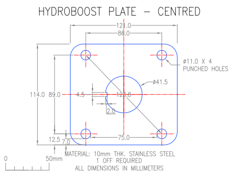
Figure 1. Hydroboost system centered template. 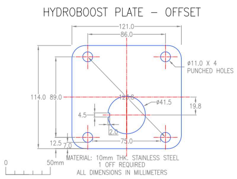
Figure 2. Hydroboost system offset template.
Step 1 – Prepare the Hydroboost unit installation
- Ensure you have all of the tools and components needed to complete this installation.
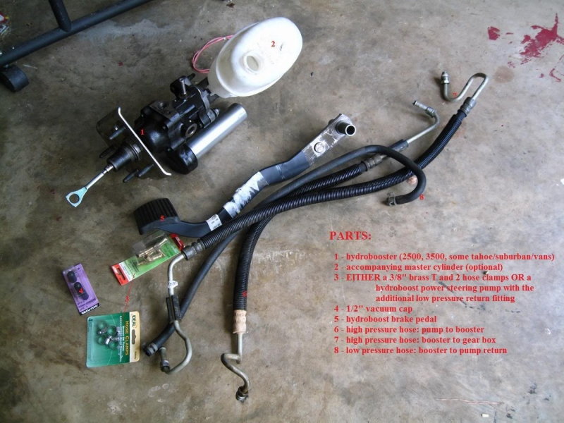
- Use the list of parts in Figure 3 as a reference throughout the installation.
Step 2 – Cap the vacuum line
- Use pliers to remove the vacuum line connected to the brake booster and intake manifold.
- Place a 1/2" cap over the vacuum port on the manifold.
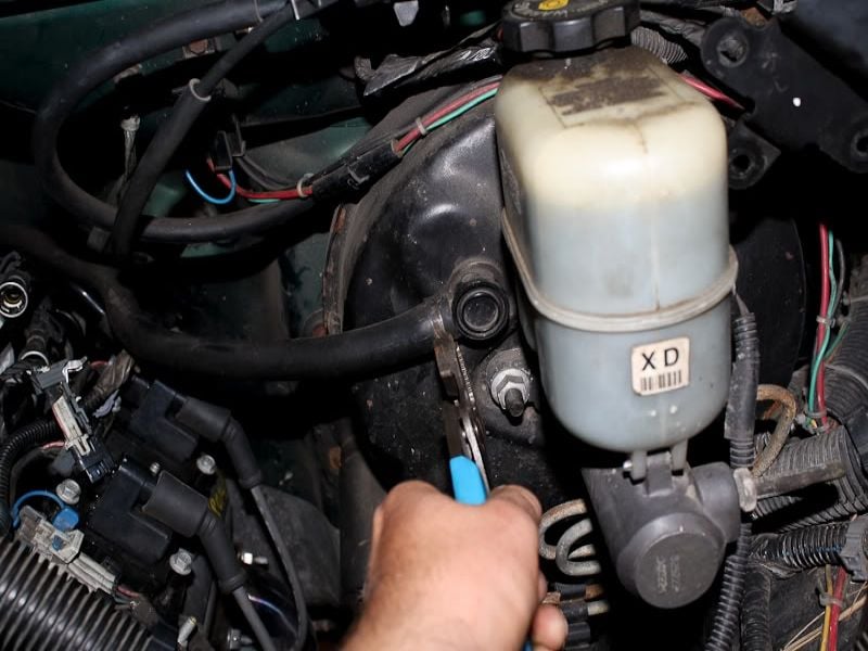
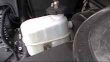
Figure 4. Remove the vacuum line from the brake booster. 
Figure 5. Cap placed on the intake manifold vacuum port.
Step 3 – Remove the master cylinder from the brake booster
- There are two 15mm nuts holding the master cylinder to the booster (refer to Figure 4). One bolt is located below the vacuum line check valve, and the other is located to the right.
- Unless you are changing master cylinders, you don't need to remove the brake lines. Place the master cylinder off to the side, and be careful not to kink the brake lines.
Step 4 – Remove the brake pedal and vacuum booster
- The brake pedal sensor and rod linkage are held in place by a small metal clip. To remove this clip, insert your flat head screwdriver between the clip and pedal rod. Twist the clip 90 degrees, then slide it down and off of the pedal rod.
- Remove the 18mm bolt holding the brake pedal to the bracket.
- Then, remove the four 15mm bolts holding the brake pedal to the vacuum booster.
- Once all bolts have been removed, the vacuum booster will slide out from the firewall.
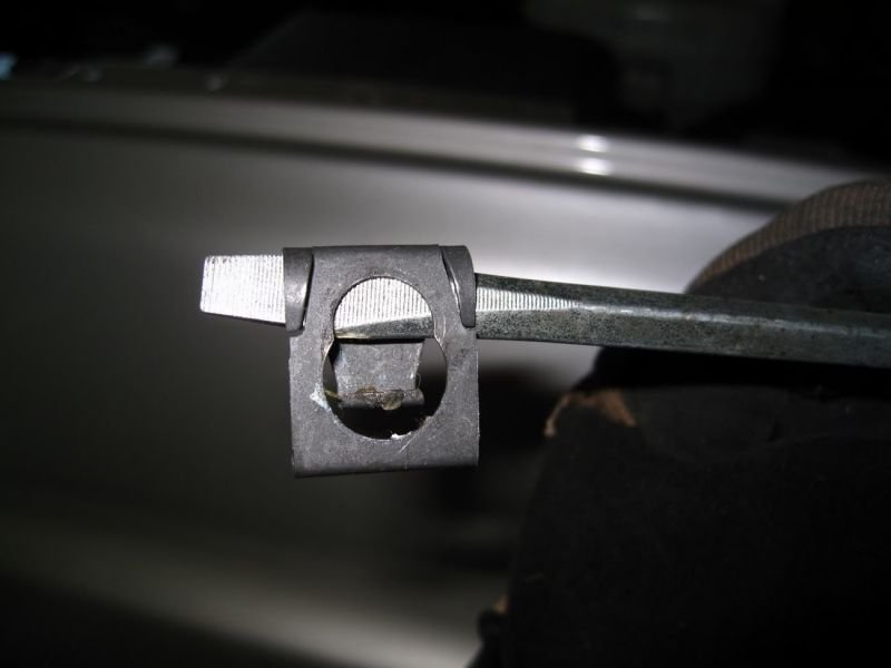
Figure 6. Metal clip securing brake pedal sensor to the rod linkage. 
Figure 7. Positions and angles (red lines) of the nuts securing brake pedal (18mm) and holding the vacuum booster to the firewall (15mm).
Pro Tip
You can use an air ratchet to speed up the removal of the nuts against the firewall.
Step 5 – Drill a hole through the firewall
Refer to Figures 1 and 2 if you decide to fabricate a plate to mount the Hydroboost unit. If you choose to drill a hole:
- Locate the detent in the firewall, and drill a hole approximately the same size as the Hydroboost unit studs.
- Inside of the truck you will find a piece of rubber attached to the firewall. Cut this piece of rubber to make a path for the offset stud.
- Mount the Hydroboost unit into place and secure it with the four 15mm bolts.
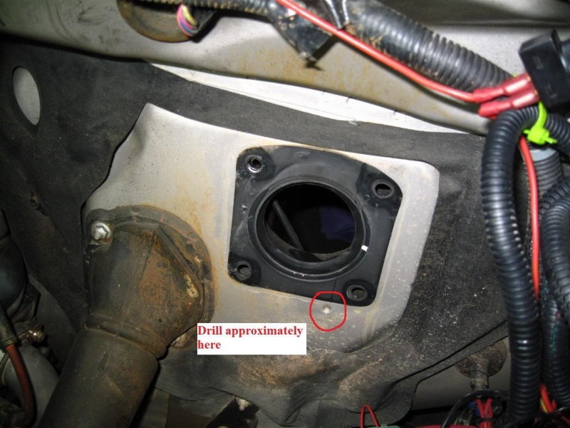
Figure 8. Drill a hole into the firewall. 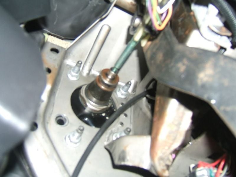
Figure 9. View of mounted Hydroboost unit from inside the truck.
Step 6 – Install the Hydroboost brake pedal
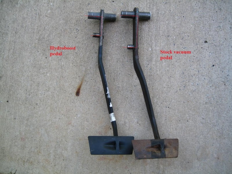
The Hydroboost brake pedal has a shorter distance between the rod studs than the stock vacuum pedal.
- Install the larger brake pedal rod to the bracket using the 18mm bolt.
- Reattach the brake sensor and Hydroboost rod to the brake pedal with the small metal clip. Do so by pressing the clip over the rod and sliding it down until the clip snaps into place.
Step 7 – Bolt on the new master cylinder
If you are using the original Hydroboost master cylinder, you can skip this step.
- Tighten down the master cylinder to the Hydroboost unit using two 15mm nuts.
Step 8 – Remove the power steering pump and install hose number 6
- Use a ratchet, extension, and 15mm socket to release tension on the tensioner pulley.
- Then slide the serpentine belt off of the pulley.
- Remove the power steering pump pulley using a pulley remover tool.
- Remove four 15mm bolts holding the pump to its mounting bracket. Three of the bolts are located on the front of the pump and one is located on the side. You should also notice that one of the bolts holds the electrical lines in place.
- Turn the pump over to gain access to the hose that runs from the pump to the gearbox. Remove this hose and connect a high pressure hose from the power steering pump to the Hydrobooster unit.

Step 9 – Install the power steering pump
- Bolt the power steering pump back into place.
- Reattach the ground line located on the side of the pump, and the electrical lines located on the front of the pump.
- Use the pulley installer tool to reattach the power steering pump pulley.
- Re-install the serpentine belt. Refer to the drive belt routing diagram located on the radiator shroud.
Step 10 – Connect the pressure hoses and Tee fitting
- Ensure that the O-rings on the hard lines are not worn out.
- Use a high pressure hose to connect the Hydroboost unit to the gearbox. Thread the hard line of the hose into the driver's side of the Hydroboost unit.
- Use a high pressure hose to connect the power steering pump to the passenger's side of the Hydroboost unit.
- Attach the Tee fitting to the low pressure return line coming from the Hydroboost unit.
- Use a razor to cut the line running from the gearbox to the cooler, and attach the line to the Tee fitting.
- Attach the Hydroboost return line to the third end of the Tee fitting.
- Use hose clamps to secure each line attached to the Tee fitting, and place the fitting between the cooler as well as power steering pump reservoir.

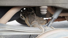
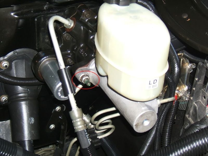
Figure 13. Hard line attached to the Hydroboost unit. 
Figure 14. Power steering system connected by the Tee fitting. 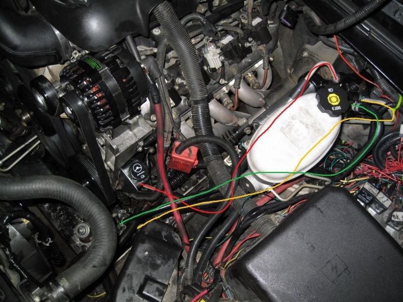
Figure 15. Route the pressure hoses and hard lines. 
Figure 16. Hydroboost system diagram. 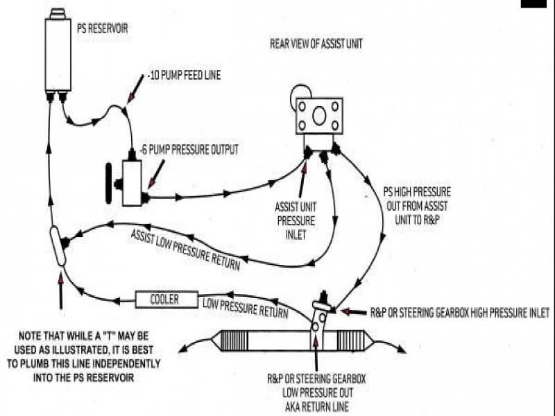
Figure 17. Routing diagram of the Hydroboost unit pressure hoses and lines.
Step 11 – Bleed the power steering system
- Double check your connections. Look for any leaking fluid or lines that have not been installed.
- Set the emergency brake and raise the front wheels off the ground.
- Fill the power steering fluid reservoir up to the max fill line.
- Turn the steering wheel from side to side about twenty times while you continuously depress the brake pedal. Keep an eye on the power steering fluid level during this process, and top off as needed.
- Start the engine. If there is still air in the system, turn the steering wheel from side to side again. Make sure not to let the steering wheel rest against the steering lock.
- Re-check the fluid level and top off as needed.
Related Discussion and Sites
- HELP! No Brakes or Power Steering on Duramaz - ChevroletForum.com
- Hydroboost Conversion, How to with Pics - PerformanceTrucks.net
- Hydroboost Conversion Install - PerformanceTrucks.net
- Hydroboost Operation Diagnosis and Repair - BrakeandFrontEnd.com