Chevrolet Silverado 2007-2013: How to Install Lift Kit
Lift or level, if your goal is to get your truck sitting higher, here's the 411 on how to get it done.
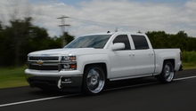
This article applies to the Chevrolet Silverado (2007-2013).
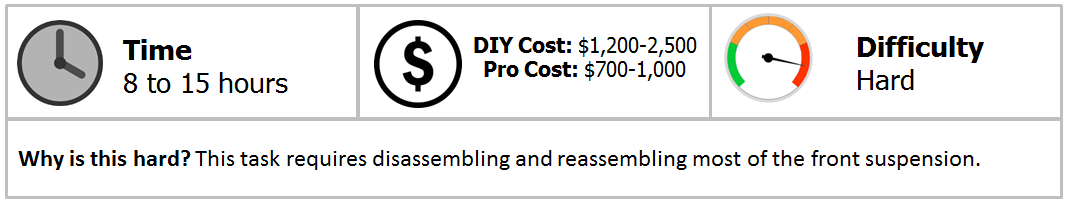
Adding a lift kit to your truck not only gives you more ground clearance for larger tires, but also greatly changes the look of your truck to set it apart from the rest. This article will cover the install of a Rough Country 7.5" lift kit. Even if you don't choose this kit for yourself, a lot of the steps will be similar. Before beginning on an install like this, it's important to make sure that you're up to the task. You don't want to get the truck torn down halfway and realize this job is too big for you to handle.
Materials Needed
- Tire Iron
- Floor jack
- 2-4 jack stands
- Wheel chocks
- Flat head screwdriver
- Full socket set
- Small sledge hammer
- Cheater bar
- Measuring tape
- Cut-off wheel
- Sander or something similar
- Straight edge
Before getting started, it is suggested reading over the instructions included with your kit multiple times to make sure you have all the necessary tools. For all steps listed below, the process will correspond to both the passenger's and driver's side of the truck unless otherwise stated.
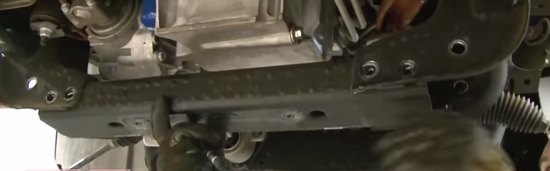
Step 1 – Remove the wheels
You'll be working on both the front and rear suspension, so you'll need to remove all the wheels and tires from the truck. If you only have two jack stands, you can start by removing the front wheels for the installation on the front suspension. If you are only removing one set of wheels at a time, make sure the wheels on the opposite end of the truck are chocked on both sides.
- Using a flat head screwdriver, pry off the center cap.
- Loosen the lug nuts using the tire iron.
- Raise the truck so that the wheel is off the ground.
- Position the jack stand under the lower control arm if in the front, and under the axle tube if in the rear.
- Remove the lug nuts and wheel.
- Lower the truck onto the jack stand.
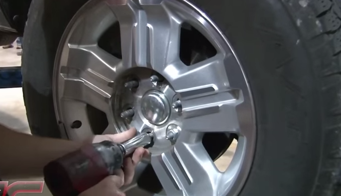
Figure 1. Remove the wheels.
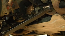
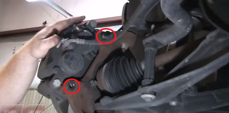
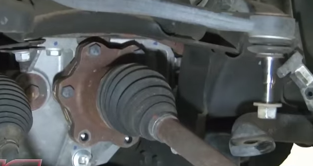
Step 2 – Front suspension: knuckle removal
- Using a flat head screwdriver, loosen the ABS wire that runs along the upper control arm by prying the clips out.
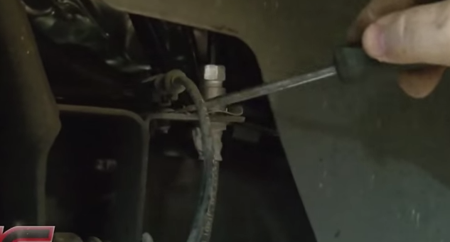
- Unplug the ABS wire.
- Unbolt the ABS wire clips from the upper control arm.
- Unbolt the brake line brackets from the knuckle.
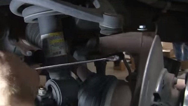
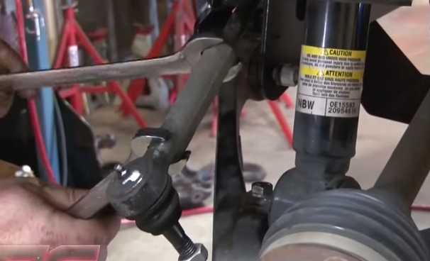
- Remove the tie rod end nut.
- Using a small sledge hammer, hit the side of the knuckle where the tie rod end bolt goes through. You will need to hit it until the tie rod end pops free. If the tie rod end is seized in place, you can apply heat to help loosen it.
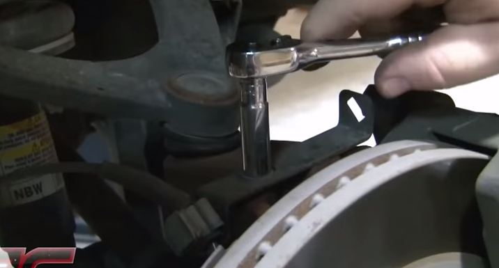
- Remove the two bolts that hold the brake caliper assembly to the knuckle. Once removed, you'll need to position the assembly somewhere where the brake line can't get stretched or damaged.
- Remove the Torx screw that locks the rotor in place.
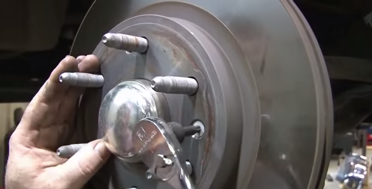
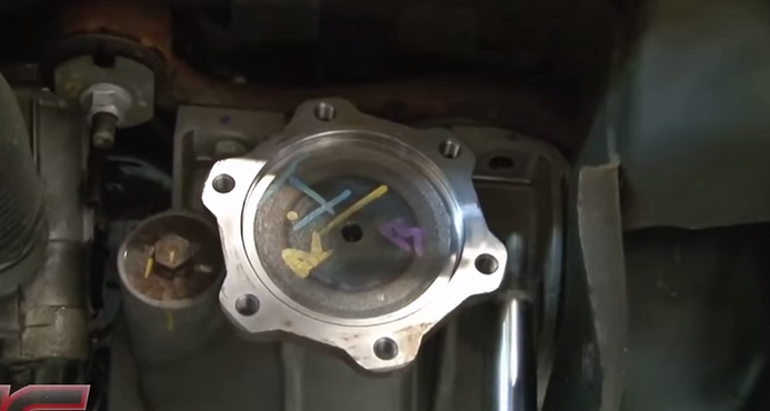
- Using the correct sized threaded bolt, thread it into one of the open threaded holes on the rotor face to apply the tension needed to push the rotor free and then remove the rotor.
- Using a flat head screwdriver and a small hammer, pry off the rotor end cap.
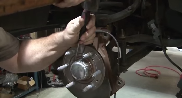
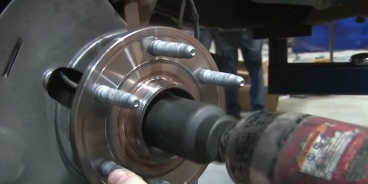
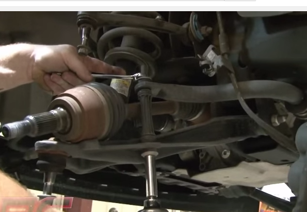
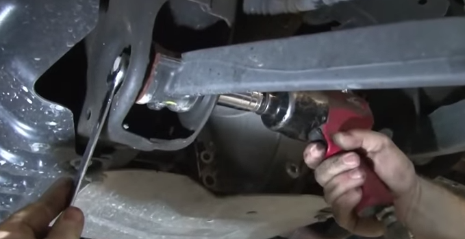
- Remove the axle nut. It's recommended to use either an air wrench or a very long cheater bar for this.
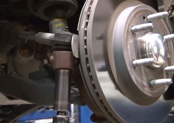
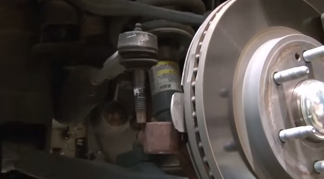
- Loosen the nuts on the upper and lower ball joints.
- With the ball joint nuts still partially threaded, hit the knuckle with the small sledge hammer to break the ball joints free.
- Once the ball joints are free, you can remove the nuts and remove the knuckle.
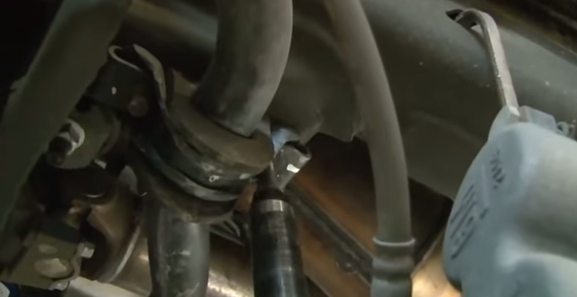
Step 3 – Front suspension: strut removal
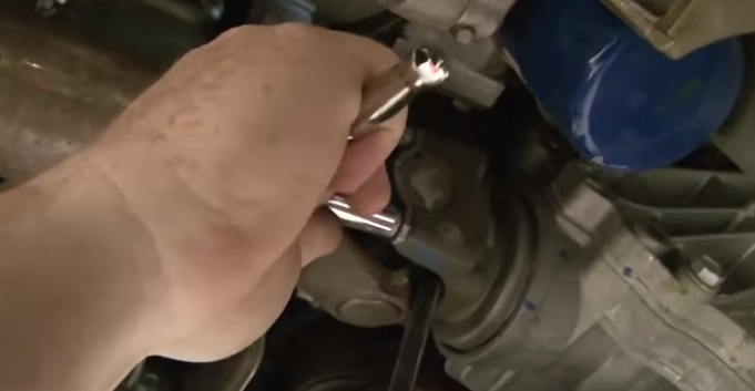
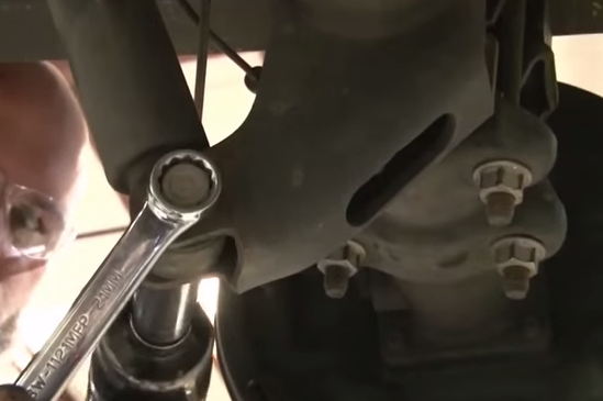
- Using a wrench to hold the nut on one end and another wrench to turn the nut of the other, remove the sway bar end link.
- Remove the two lower strut bolts.
- Remove the upper strut nuts.
- Remove the strut from the vehicle.
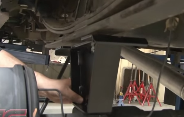
Step 4 – Front suspension: differential removal
- Remove the six axle shaft bolts, and then remove the axle shaft.
- Remove the lower control arm bolts, and then remove the lower control arm.
- Remove the bolts holding the sway bar brackets.
- Remove the sway bar from the truck.
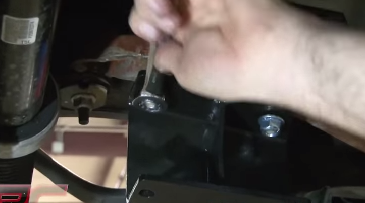
- Remove the factory skid plate by unbolting it (one side only).
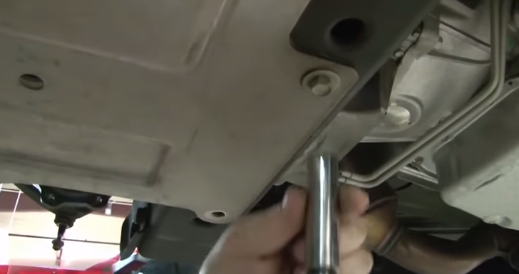
- Remove the rear crossmember from the truck by unbolting it (one side only).
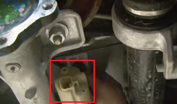
- Unplug the electrical connector on the differential near where the axle shafts attach.
- Remove the bolts attaching the front drive shaft to the differential. It is suggested finding something to support it on while you work (only one side).
- Position a jack or have a helper ready to hold the differential for the next step.
- Remove the four differential bolts (two in the front, two in the back).
- Remove the differential from the truck.
Step 5 – Front suspension: install modifications
The following steps will be specifically noted for one side or the other.
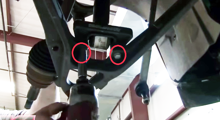
- On the driver's side lower control arm pocket, measure over 3/4" from the edge of the rear crossmember bolt hole, and mark it.
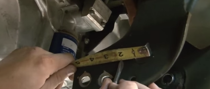
- Using a straight edge, mark a vertical line up the control arm pocket from the mark you just made.
- Using a cut-off wheel or something similar, cut along the line you just marked.
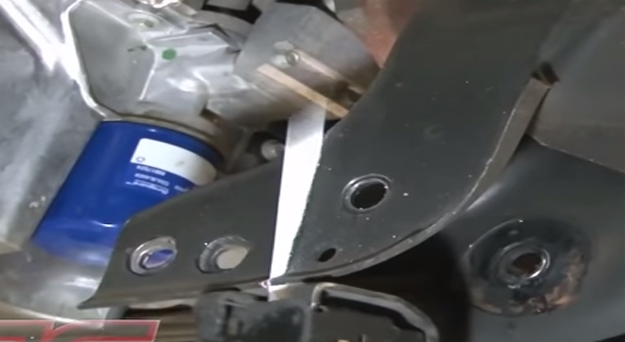
Figure 23. Cut along the marked line. 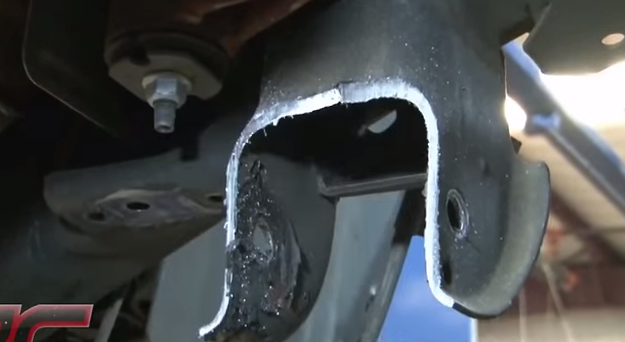
Figure 24. Cut off here, as seen above.
- Using a sander or something similar, clean up the rough edges from the cut you just made.
- Trim about a 1/2" out of the lower control arm mount.
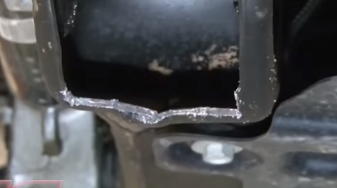
- Clean up the rough edges from the cut.
Step 6 – Front suspension: install lift kit
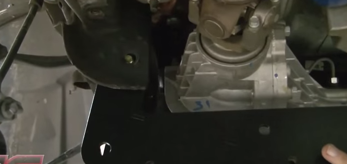
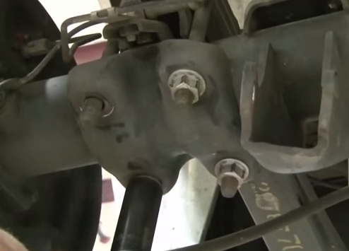
- Install both the passenger's and driver's side differential drop brackets.
- Raise and re-install the front differential onto the drop brackets.
- Reconnect the differential electrical connector.
- Re-install the front drive shaft to the differential.
- Install the new front crossmember into the front lower control arm mounts.
- Install the new rear crossmember into the rear lower control arm mounts.
- Re-install the lower control arms, and then fully tighten the crossmembers.
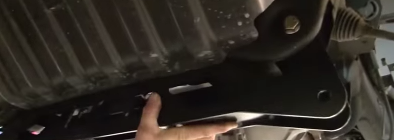
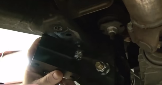
- Install the skid plate onto the crossmember mounts.
- Install the sway bar drop brackets.
- Re-install the sway bar onto the drop brackets.
- Install the sway bar end links onto the control arms.
- Re-attach the axle shafts to the differential using the spacer included with the kit.
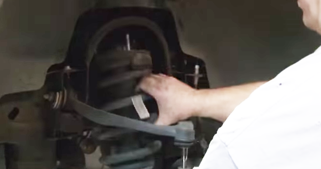
- Install the studs on top of the strut spacers. You'll need to tighten the nuts down on the bolts to pull the bolts into place, and then you can remove the nuts.
- Install the strut spacer onto the strut.
- Re-install the strut onto the truck. Tighten the upper and lower strut bolts.
- Tighten the sway bar end links.
- Unscrew the tie rod end from the tie rod jam nut.
- Clean up any rough edges from the cuts you just made.
- Re-install the tie rod ends.
- Remove the knuckle from the factory knuckle assembly.
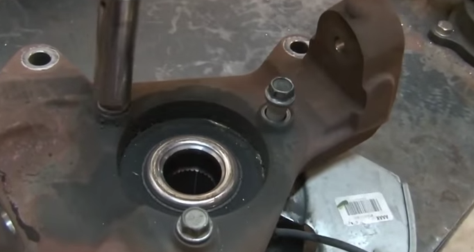
- Install the new knuckle onto the knuckle assembly.
- Re-install the knuckle assembly onto the upper and lower ball joint.
- Tighten the upper and lower ball joint.
- Re-install the axle nut.
- Re-install the rotor end cap.
- Re-install the rotor by tightening it into place with the Torx screw.
- Place the ABS cable back into its connectors on the upper control arm, and then plug it back in.
- If necessary, use a zip tie to secure the ABS wire out of the way.
- Re-install the brake caliper.
- Re-install the tie rod end into the knuckle.
- Install any necessary brake line drop brackets.
Step 7 – Rear suspension: removal
- Remove rear shocks by removing the bolt at both the bottom and the top.
- If you don't have the truck on a lift, place a jack under the frame on the side of the truck that you are removing the U-bolts from in the next step. This will support the truck once the axle is free.
- Remove U-bolts and U-bolt plates. If you do not have the truck on a lift, it is suggested only completely removing one side at a time and leaving the other side partially loosened.
- You now have two options, you either lower the rear axle enough to remove the stock block (recommended), or you can raise the truck by the frame enough to get the stock block out.
Step 8 – Rear suspension: install
- Install new block in place of the factory one.
- Install the new U-bolts and U-bolt plate and then tighten.
- Install the new rear shocks.
Step 9 – Finishing up
Once you have the lift kit installed, you can go ahead and re-install all the tires. The next thing you need to do is go straight to an alignment shop. There's a very slim chance that your alignment maintained itself after the install, so you'll need to get a new one to make sure your tires don't wear unevenly. The alignment will also help to make driving the truck as safe as possible.
Featured Video: Installing Lift Kit on Silverado
Related Discussions
- Lift Kit Question - ChevroletForum.com
- Lift Kit Help - ChevroletForum.com
- Lift Kits - ChevroletForum.com
- Rough Country Lift Kit: Good or Bad? - ChevroletForum.com
- Removing Three-Inch Body Lift - ChevroletForum.com