Chevrolet Silverado 1999-2006: How to Replace Upper Control Arm
One result of serious truck driving is the wearing out of one or more upper control arms, resulting in the added failure of the connection bushings, the ball joints, or all of the above. This article walks you through the steps and tasks required to change your Silverado's upper control arm.
This article applies to the Chevrolet Silverado 1500 (1999-2006).
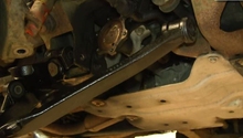
An upper control arm can go bad if the bushings holding it to the frame brackets fail or if the ball joint attaching the control arm to the wheel knuckle wears out. An indication that the bushings have worn out is if there is side-to-side movement of the control arm, where the bracket attachments are connected on the frame. An indication that the ball joint connecting the control arm to the steering knuckle has worn out is if you feel any up-and-down play between the control arm and its attachment point at the wheel knuckle.
The upper control arm bushings can be replaced using a bushing removal tool or bushing press. However, if the ball joint has failed, the entire upper control arm needs to be replaced because this ball joint is not serviceable. Bushing removal kits can be rented from an auto supply store, often at no cost to customers.
Materials Needed
- 10, 21, and 22mm sockets
- Ratchet and extension
- 18 and 21mm long, open end/box end wrenches
- Marker/paint stick
- Torque wrench
- Floor jack and jack stands
- Wheel chocks
- Grease/grease gun
- Hammer (large)
- Air hammer (optional, depending on the age and condition of the vehicle)
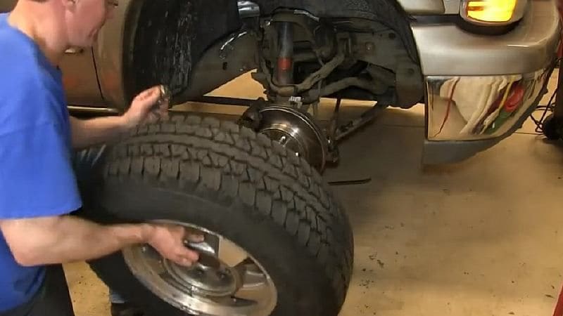
Step 1 – Remove the front wheel
- Park the truck on level pavement, engage the emergency brake, and chock the rear tires to prevent the truck from rolling backwards.
- Break the lug nuts loose on the wheel where the control arm is to be replaced.
- Use a floor jack to raise the front of the vehicle, and place jack stands under the frame rails just behind the lower control arm mounts.
- Lower the truck onto the jack stands, and make sure the stands are not tilting in any direction.
- Remove the lug nuts and the front wheel.
(Related Article: How to Jack Up Your Silverado - Chevroletforum.com)
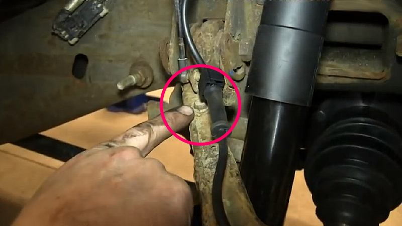
Step 2 – Remove the brake line and ABS wire attachment bolts
- Using a 10mm wrench, remove the bolt that holds the brake line to the upper control arm.

- Remove the bolt holding the ABS wire mount to the upper control arm.
Step 3 – Mark the cam plates
Each camber bolt can slide back-and-forth in the bracket’s oblong hole to allow adjustment of the wheel’s camber and caster. The tab/pin’s location in the spiral groove of the cam plate sets the bolt’s horizontal location during wheel alignment.
If your vehicle has never had a front end alignment, you may find plastic retainers force-fit into the cam slots on the attachment brackets. If all four sides of the control arm attachment points have plastic inserts in the cam plate, leave the inserts in when you remove the cam plate and upper control arm. Make sure not to mix up which plates go on which side of the bracket.
Alternatively, as these retainers were used by the factory during assembly, you can pry them out with a small screwdriver. Don’t worry if they break when prying them out as they will all be discarded when you realign the front end of your vehicle.
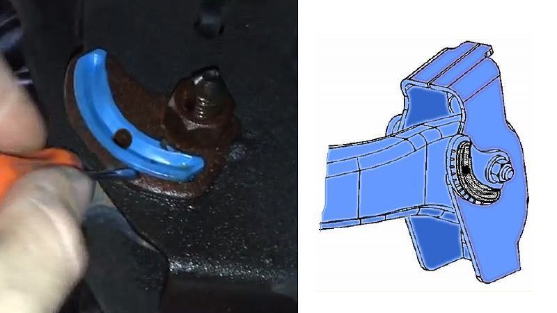
For the cam plates that don't have a plastic retainer:
- Use a marker or paint stick to mark the position of the tab on each cam plate's spiral groove. You can mark the position on either side of the upper control arm attachment brackets.
- Then remove the two large camber bolts. Make sure not to mix up the plates or their locations when you attach the new control arm.
Pro Tip
Regardless of how close you get the cam plates back to their original position, you will still need to have the front end realigned after replacing a control arm. Getting the plates back into their marked position could not only make that job go faster, it could also make the drive to the alignment auto shop a lot smoother.
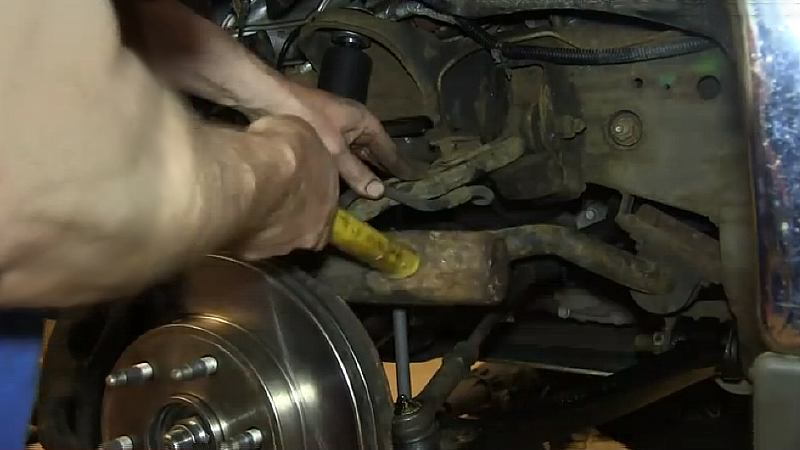
Step 4 – Loosen the upper ball joint
- Loosen the 18 mm nut securing the control arm's ball joint to the wheel knuckle.
- Unscrew the nut a few turns, but don't remove it entirely.

- Using a hammer, hit the side of the knuckle attached to the upper control arm's ball joint. Continue hitting the knuckle until the ball joint has been freed.
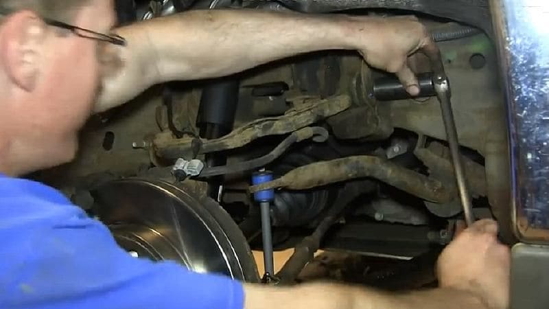
Step 5 – Remove the cam plates
- Remove both 21mm nuts located outside of both control arm fastening brackets.
- Then remove the two cam plates that were held in place by the nuts.
- Remember which cam plates came off which side.
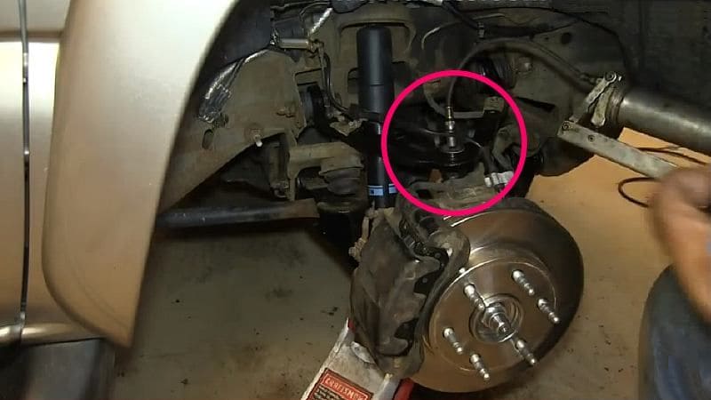
Step 6 – Detach the ball joint
- Place the floor jack underneath the wheel knuckle and jack it up three inches (7.5 cm) or so.
- Remove the 18mm nut securing the upper control arm ball joint to the knuckle.
- With the nut removed, pull the control arm free from the knuckle.
At this point there is no tension on the camber bolts of the two attachment brackets.

Step 7 – Remove the old upper control arm
- Remove the 21mm bolts on both of the control arm fastening brackets. Again, remember which cam plates came off of which side.
- Swivel the control arm up and down as you pull on it to free it from the brackets.
Pro Tip
If one or both of the bolts are difficult to remove, re-fasten the nut but don’t tighten it completely. Then pound on the nut with a large hammer (or better yet, an air hammer) to loosen the bolt. When the bolt breaks loose, take the nut off again and remove the bolt.
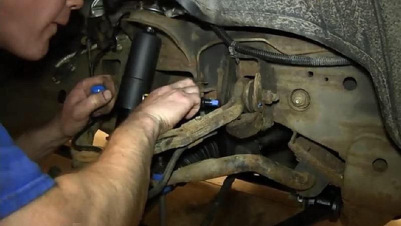
Step 8 – Install the new upper control arm
- Clean the connection brackets of any loose rust and road film.
- Push the new control arm into the two brackets.
- Replace the cam plates for each side as you are replacing the bolts. Don't tighten the 21mm nuts just yet.

- Angle the control arm ball joint end down into the wheel knuckle attachment location.
- When the ball joint is pressed down in position, re-install and hand-tighten the 18mm nut. Do not fully tighten the nut just yet.

Step 9 – Tighten the control arm bolts and ball joint nut
- Making sure the paint markings indicate that the cam plates are back to their original marked position on both sides, tighten the 21mm control arm nuts to their proper torque rating.
- Then tighten the 18mm ball joint nut down to the proper torque rating.
Step 10 – Complete the installation
- Re-install the 10mm bolts that secure the brake line and ABS wire to the upper control arm.
- Use a grease gun to fill the Zerk fitting on the ball joint (located at the end of the control arm) with grease until it backs up.
- Lastly, mount the wheel and re-install the lug nuts. Lower the front end and tighten the lug nuts in an alternating pattern to 100 ft-lbs (136 N-m).
Featured Video: How To Install/Replace Upper Control Arm
Related Discussions
- Discussion About Replacing the Upper Control Arm Bushings - Chevroletforum.com
- Discussion About Replacing Ball Joints -Chevroletforum.com