Chevrolet Silverado 1999-2006: How to Install Trailer Brake Controller
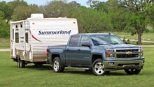
If your trailer has electric trailer brakes, you will benefit by installing a trailer brake controller. This will give you precise control over how much braking power you want from your trailer brakes.
This article applies to the Chevrolet Silverado 1500 (1999-2006).
A trailer brake controller displays the voltage level on the wiring traveling from your truck's brake pedal to the trailer's electric brakes. The higher this voltage level is, the harder your trailer brakes are being applied. Most trailer brake controllers have an adjustable gain function, letting you fine tune your trailer brakes' sensitivity. The trailer brake controller is most commonly mounted inside the truck cabin below the dashboard. It is connected to an electrical harness that is also connected to an electrical junction box behind the brake pedal. Keep reading to learn how to install a trailer brake controller on your Silverado 1500.

Materials Needed
- Power drill
- Phillips/flat head drill bit
- Metric or SAE socket set
- Ratchet 3/8" or 1/2"
- Zip ties
- Pliers
- 40-amp fuse
When purchasing the controller, be sure that the plug and play wiring harness (trailer brake controller to junction box) is included with the order.
Step 1 – Mount the trailer brake controller
Your mounting locations are limited to the length of the electrical harness. When you find a suitable location, mount the controller bracket by screwing it into the dash panel with your power drill.
Now slide the controller into the mount. Depending on which controller you bought, it may or may not have pre-drilled holes. Set the controller into the bracket at your desired position and drill screws into the side of the controller body (refer to your controller's instructions for the specific location).

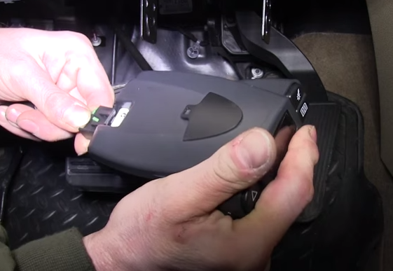
Step 2 – Remove the junction box cover
This junction box is located behind the brake pedal at the left corner of the floorboard area. There is a thumbscrew on the middle of the cover. Turn it counter-clockwise to remove it, then pull the cover off the junction box. There are two retaining clips on the left side and top of the cover that must be lifted slightly while you pull the cover.
Step 3 – Plug the provided wiring harness into the junction box
Plug the harness into the uppermost port second to the left. You will feel and hear it snap into place.
Now re-install the junction box cover. Route the wiring harness out of the junction box through the upper side of the cover.
Step 4 – Plug remaining harness connector into the trailer brake controller
Zip tie the wiring harness up and away from the floor board, then plug the connector into the back of the controller.
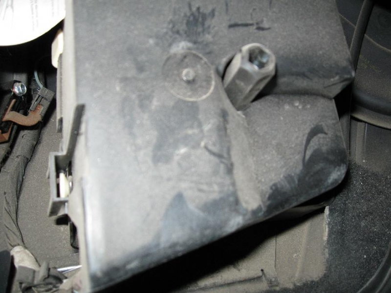
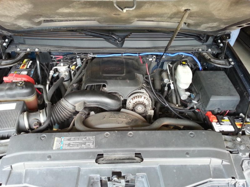
Step 5 – Remove the upper portion of the under hood fuse box
The fuse box is located on the driver's side directly behind the headlight. The cover is a two-piece design. The upper section can be pulled off the lower larger section.
Step 6 – Removed the curved bracket behind the under hood fuse box
This bracket is held in place by four bolts.
Step 7 – Remove the lower engine bay fuse box cover
The lower portion of the fuse box cover simply lifts up and away from the fuse box.
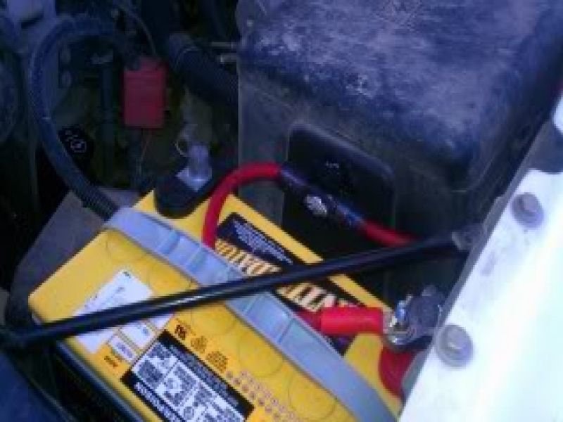
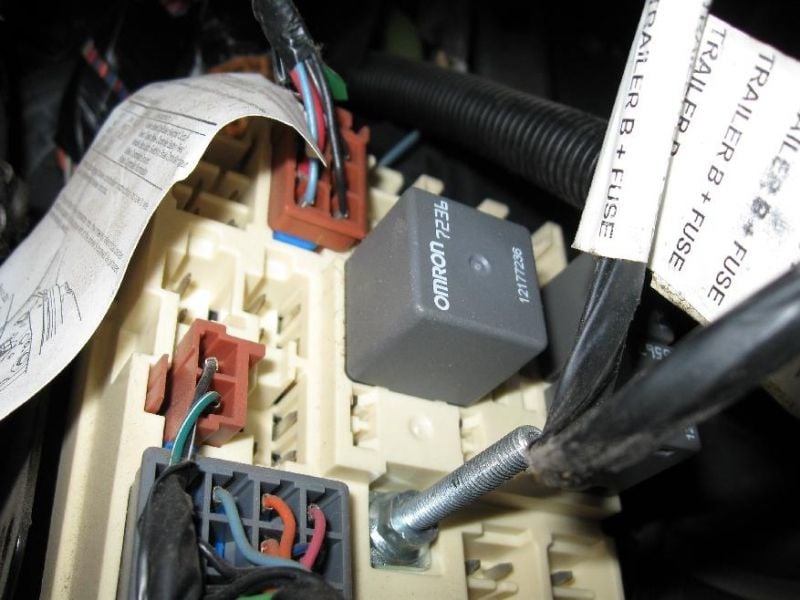
Step 8 – Install the two red and blue wires; install a 40-amp fuse
Once the lower cover is removed, you will see two metal wire connection posts on the side of the fuse box opposite of the fender. Two red wires with circular eyelet terminal rings go onto these terminals. They are beside the fuse box if they are not already installed onto the connection posts. The larger of the two goes onto the post closer to the front of the truck. You will need to secure these wires down with nuts.
- You will also see two blue wires with matching connectors next to the fuse box. If these are not snapped together, do so now.
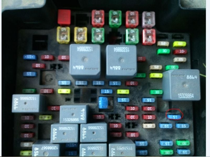
- In the fuse box you may see a solid red fuse plug. In Figure 5, this fuse plug is at the upper left corner of the fuse box. Remove this plug if your truck has it installed.
- Now install a 40 amp fuse into this location.
- Finish by re-installing the fuse box covers and curved bracket. The trailer brake controller is now fully installed!
Featured Video: Installation of a Trailer Brake Controller on a 2004 Silverado
Related Video
- Installation of Trailer Brake Controller 2003 Silverado - Youtube.com